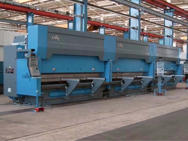
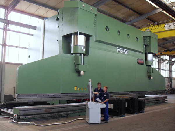
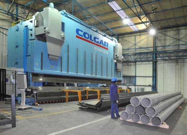
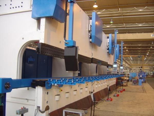
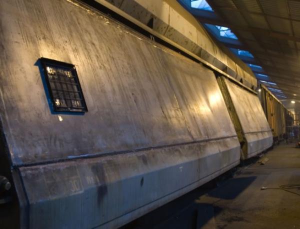
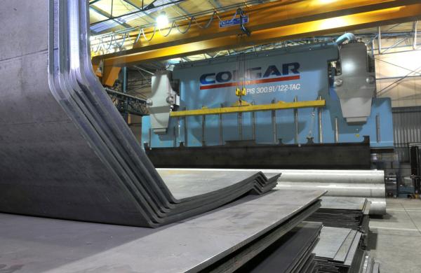
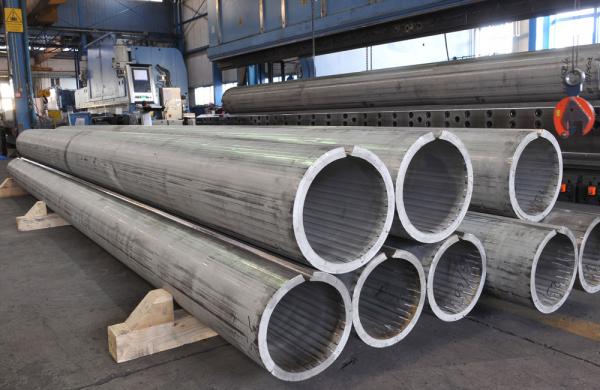
BendingMaximum bend length 28 500 mm
Thickness 1 to 250 mm
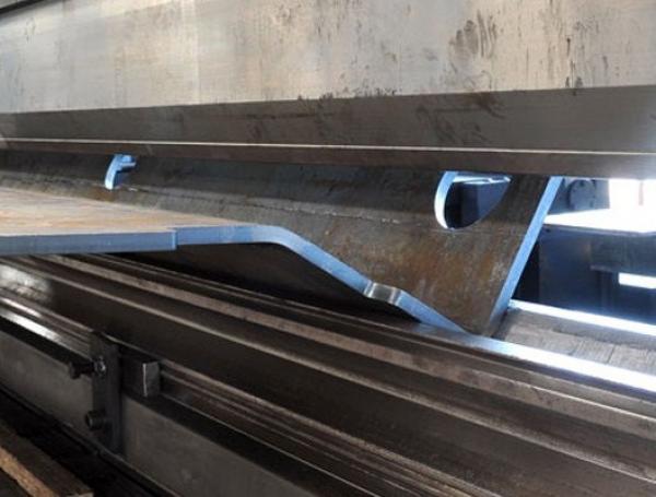
Throat 1 500 mm Material Steels, stainless steels, aluminium Equipment 7 press brakes : 2 x 15 000, 7 500, 6 350, 4 000, 3 000, 2000
Power 5.700 tonnes
Programming Graphic NC
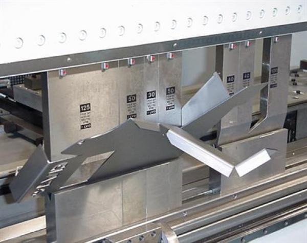
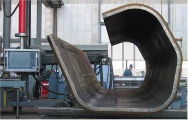
Creations; special profiles on plan,
prototypes and series,
custom work. -Bending technique
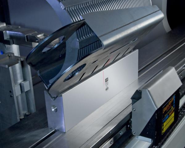
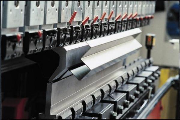
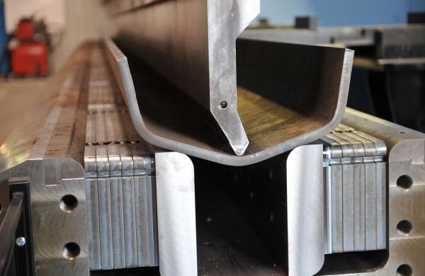
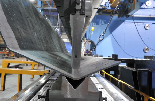
Air bending Air bending is an operation involving three tooling points:
- The two edges of the V.
- The end of the punch
The shape of the die is important. The V was adopted simply because it is the most simple and resistant shape to make.
The neutral axis is not elongated. The metal maintains its zone of plastic deformation. It is therefore necessary to bend at an angle that is tighter than the required angle, to compensate for sheet springback. Generally, for bends at 90°, the dies and punches are sized to 85°. The inner radius obtained will be approximately equal to 1/6 of the width of the V used (except in cases in which the punch has a greater radius). The tonnage to be applied is either determined by using a bending chart (to be increased by 15 to 20%),or determined irectly by numerical control from the data: sheet thickness, mechanical strength of the sheet, bend length and V opening. The best result may be obtained with Vs of a width approximately 8 to 12 times the thickness of the sheet. It is important to note that for medium and large sheets, an inner radius that is too tight would reduce the mechanical strength considerably because he outer area of the bend could be subjected to substantial elongation. Air bending requires less machine capacity than coining, the tonnage to be applied changing in inverse proportion to the V. Moreover, using one single tool enables the creation of different angles. For a given adjustment, the angle obtained will be influenced by the following variable elements:
- Tolerance of the sheet thickness
- Elastic characteristics of the material, this may vary on the same sheet at different points of the bend, more particularly at the edge of the sheet. It also varies according to the direction of rolling.
- Flexure of the apron and slide generating an angle in the middle that is not as tight as that of the columns, hence the necessity to equip the machines with apron crowns for accurate bending.
- For small Vs (bending of sheets of small thickness), the angular differences are substantial. For example a variation of penetration of 6/100 millimetre in a V of 8 mm for a theoretical bend at 90° represents approximately 0.8°.
-Bending technique
When calculating sheet figures for bending, there is no absolute formula. The rules vary according to the various bending parameters and characteristics of the sheets. The figures can nevertheless be determined using the elements below: in the bent portion of the sheet, the non-deformed fiber (neutral fiber) is no longer in the middle of the thickness, but has moved towards the inner surface of the bend (refer to diagram below):
The radius of this neutral fiber is therefore equal to: r + ke . The table below gives the values of k according to the standard DIN 6935. r/e > 0.65 >1 >1.5 >2.4 >3.8 k 0.3 0.35 0.4 0.45 0.5. The value of the bend allowance (L) of the bent sheet is calculated as follows: L=A+B- C | 


")